
Resistance and the LED
💡 Introduction to Light Emitting Diodes (LEDs)
In our journey through the components of IoT, we encounter an essential component known as the Light Emitting Diode, or LED for short. Unlike traditional incandescent bulbs, which generate light through heat, LEDs produce light by the movement of electrons in a semiconductor material. This makes LEDs more energy-efficient and longer-lasting, making them a popular choice in various applications, from indicator lights to full-fledged displays.
So in essence, a LED is a device that can convert electrical signals into physical movements or effects. To put it plainly,the LED is the first actuator you will encounter.
Understanding Forward Voltage (
When working with LEDs, it's crucial to consider two key parameters: forward voltage (
Forward voltage (
Maximum current (
Nominal current (
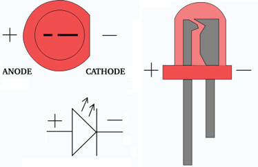
Anode and Cathode Orientation
Like many electronic components, LEDs have polarity, meaning they must be connected in a certain orientation to function correctly. LEDs consist of two terminals: the anode and the cathode.
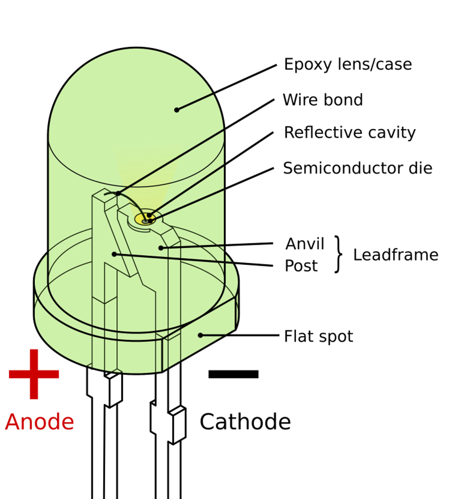
The anode is the positive terminal of the LED and is typically indicated by a longer lead or a flattened side on the LED's housing. Electrons flow into the LED through the anode during operation.
Conversely, the cathode is the negative terminal and is usually identified by a shorter lead or a notch on the LED's housing. Electrons exit the LED through the cathode.
Understanding the orientation of the anode and cathode is crucial when incorporating LEDs into circuits to ensure proper functionality and prevent damage. The anode should be connected to the positive side of the power source (e.g., GPIO pin), and the cathode should be connected to the negative side.
🧱 Introduction to Resistance
In our exploration of electronics, we've already learned about GPIO, current, and voltage. Now, let's delve into another fundamental concept: resistance. Imagine resistance as a sort of obstacle that affects the flow of electrons in a circuit. Just as friction slows down a rolling ball, resistance limits the flow of electric current.

Resistance is essentially the opposition to the flow of electric current within a material. Every material has some degree of resistance. Some materials, like metals, have low resistance, allowing electrons to flow easily. Others, like rubber or plastic, have high resistance, hindering the flow of electrons.
Ohm's Law
To understand resistance better, we turn to Ohm's Law, named after the German physicist Georg Simon Ohm. Ohm's Law states that the current (I) flowing through a conductor between two points is directly proportional to the voltage (U) across the two points and inversely proportional to the resistance (R) between them. In mathematical terms:
Here, ( U ) represents voltage in volts (V), ( I ) represents current in amperes (A), and ( R ) represents resistance in ohms (Ω).
You can see an interactive simulation of this formula in action at this link.
In practice: using and selecting a resistor
Now, let's apply this to a practical scenario: connecting a Light Emitting Diode (LED) to our Orange Pi via GPIO.
🔥 LEDs are sensitive components that can easily burn out if too much current flows through them. To prevent this, we need to be able to select the correct resistor. 🔥
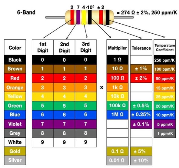
When selecting a resistor, it's crucial to understand the color coding system used to denote resistance values. Typically, resistors have four or five colored bands that represent specific digits and a multiplier. The first two bands indicate the significant digits, the third band represents the multiplier (which determines the magnitude of resistance), and the fourth band indicates tolerance.
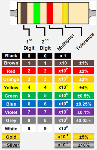
To decode the resistance value, you need to look at the:
- First two bands: These represent the significant digits of the resistance value. Match the colors to their corresponding numbers: black (0), brown (1), red (2), orange (3), yellow (4), green (5), blue (6), violet (7), gray (8), and white (9).
Third band (multiplier): This band indicates the power of ten to which the significant digits must be multiplied. Match the color to its corresponding multiplier: black (1), brown (10), red (100), orange (1,000), yellow (10,000), green (100,000), blue (1,000,000), violet (10,000,000).
Fourth band (tolerance): This band specifies the tolerance of the resistor, indicating how much the resistance value might deviate from the stated value. Common tolerance values are typically represented by the following colors: brown (±1%), red (±2%), green (±0.5%), blue (±0.25%), violet (±0.1%), and gray (±0.05%).
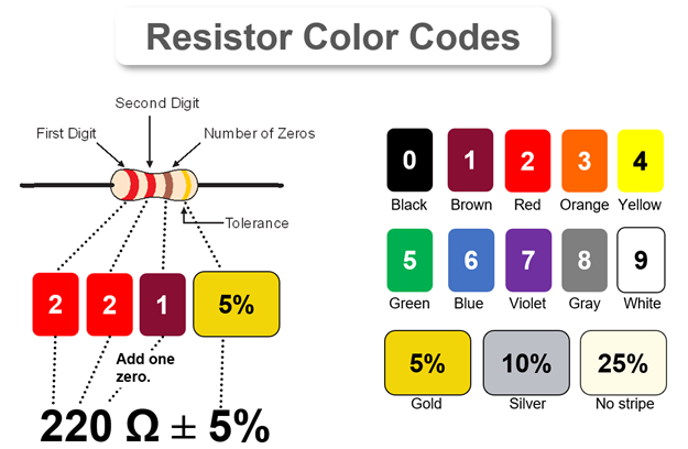
For instance, if you have a resistor with the color bands brown, black, red, and gold, you can decipher its resistance value as follows:
- The first band (brown) represents the digit 1.
- The second band (black) represents the digit 0.
- The third band (red) represents the multiplier 100 (or 10^2).
- Therefore, the resistance value is 10 * 100 = 1000 ohms (1 kiloohm), with a tolerance of ±5%.
There are also resistors with 6 bands. These are set-up in the following way:
🛠 Connecting an LED to the Orange Pi
🦺 Safety Precautions🦺 :
- Double-check connections before powering on.
- Avoid touching exposed wires while the circuit is powered.
- Use a current-limiting resistor to protect the LED.
Identify LED Specifications
Begin by determining the forward voltage
- Forward Voltage (
): The forward voltage of an LED is the voltage required to make it conduct electricity and emit light. It's a crucial parameter to ensure the LED operates correctly and efficiently. You can find this information in the datasheet provided by the manufacturer or by using a multimeter to measure it directly. - Nominal Current (
): This is the current that the LED is designed to operate at for optimal performance and longevity.
For our case
- Forward Voltage (
): 2.2 volts - Nominal Current (
): 12 milliamperes (mA)
Determine Operating/Supply Voltage
Check the GPIO output voltage of your Orange Pi. This is typically around 3.3V. To find the GPIO output voltage of your Orange Pi, you can refer to the technical specifications provided in the user manual or the manufacturer's website. Alternatively, you can measure the voltage using a multimeter while the Orange Pi is powered on and a GPIO pin is set to output mode.
For our case
The GPIO output voltage of the Orange Pi 3 is around 3.3 volts.
Calculate Resistance
Use Ohm's Law
For our case
As we said we'll use Ohm's Law
Substituting the values:
In practice, if we don't have a 91.67 ohm resistor available, we need to choose the closest standard value. If the closest available resistor is 220 ohms, it would still provide some current limiting, although it may not be as precise as a 91.67 ohm resistor. Therefore, we would use a resistor with red, red, brown, and gold bands, indicating a resistance of 220 ohms.
Connect Components
Use jumper wires to connect the components to the GPIO pin 2 of the Orange Pi. We will use a breadboard for this, a component that allows you to create temporary electrical connections between electronic components and single board computers or microcontrollers. It has many holes arranged in rows and columns, which are internally connected by metal clips. You can insert the leads or pins of the components into the holes to make a circuit.
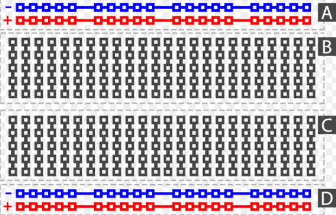
The rails (A & D) and columns (B & C) are the two types of connections on a breadboard. The rails (A & D) are the long horizontal rows on the sides of the breadboard, usually marked with red and black lines. They are used to provide power and ground to the circuit.
The columns (B & C) are the short vertical rows in the middle of the breadboard, usually marked with numbers. They are used to connect the components to each other. Each column is electrically isolated from the adjacent columns, but connected to the holes in the same column.
For more information you can check this video.
When connecting the LED and resistor in series, it's important to ensure the correct polarity.
LEDs have two leads: the longer one is the anode (positive terminal), and the shorter one is the cathode (negative terminal). The anode should be connected to the positive side of the power source (e.g., GPIO pin), and the cathode should be connected to the negative side. If you're unsure which lead is which, you can usually identify the cathode by a flat edge on the LED's plastic casing or a shorter lead.
When connecting the resistor on the breadboard be sure to not make this mistake:
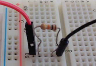
Instead do:
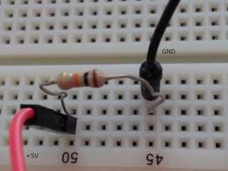
For our case
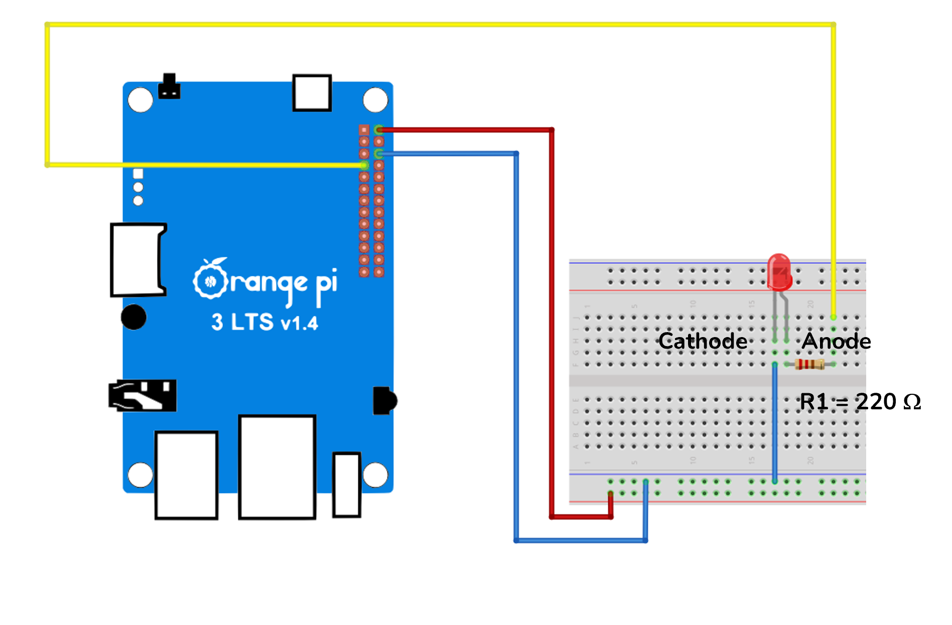
This diagram shows how your setup should look. As you can see the GPIO2 of the Orange Pi 3 is connected to the breadboard.
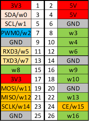
Connect 5V (pin 2), Ground (pin 6) and GPIO2 (pin 7), which is named w2 on the chart, in the following way. Notice that the 5V is connected to the rail but we are not using it in our connected circuit.
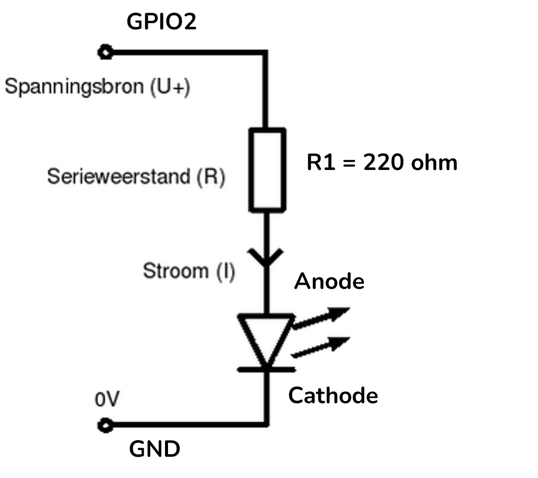
Which as an electrical diagram looks like this:
Using WiringPi to Control GPIO
Now use WiringPi (Python) to write a script that controls the GPIO pins to turn the LED on and off.
You can do so with the following commands:
- Set the wiringPi GPIO2 as an output pin. This means that the pin will be able to send a signal to the LED.
$ gpio mode 2 out- Set the output GPIO2 to a high state, which means that it sends a voltage of 3.3V to the LED to make it light up.
$ gpio write 2 1- Sets the output GPIO2 to a low state, which means that it sends a voltage of 0V to the LED which makes it not light up anymore.
$ gpio write 2 0You can also write a Python script that uses WiringPi as a library in your code:
# Import the time, wiringpi and sys modules
import time
import wiringpi
import sys

# Define a function called blink that takes a pin number as an argument
def blink(_pin):
   wiringpi.digitalWrite(_pin, 1)    # Write 1 ( HIGH ) to pin, which turns on the LED
   time.sleep(0.5)                   # Wait for 0.5 seconds
   wiringpi.digitalWrite(_pin, 0)    # Write 0 ( LOW ) to pin, which turns off the LED
   time.sleep(0.5)                   # Wait for another 0.5 seconds

# Initialize the wiringpi library and set pin 2 to output mode
print("Start")                        # Print "Start" to the console
pin = 2                               # Assign the value 2 to the variable pin
wiringpi.wiringPiSetup()              # Initialize the wiringpi library
wiringpi.pinMode(pin, 1)              # Set pin 2 to mode 1 ( OUTPUT ), which means it can send signals

# Blink the LED connected to pin 2 for 10 times
for i in range(0,10):                 # Create a loop that repeats 10 times
   blink(pin)                        # Call the blink function with pin 2 as the argument

# Print "Done" to the console when the loop is finished
print("Done")                         # Print "Done" to the console when the loop is finished