
Understanding GPIO, Current, and Voltage
What is GPIO?
Before we delve into the intricacies of current and voltage, let's first understand what GPIO is about. GPIO, which stands for General-Purpose Input/Output, is like a versatile Swiss Army knife for an Embedded platform like an Orange Pi 3. It's a set of digital pins that can either receive information (input) or send out signals (output) by adjusting the voltage, allowing us to interact with the physical world. Think of it as the bridge that connects the digital realm of our computer to the analog world of sensors, lights, and motors.
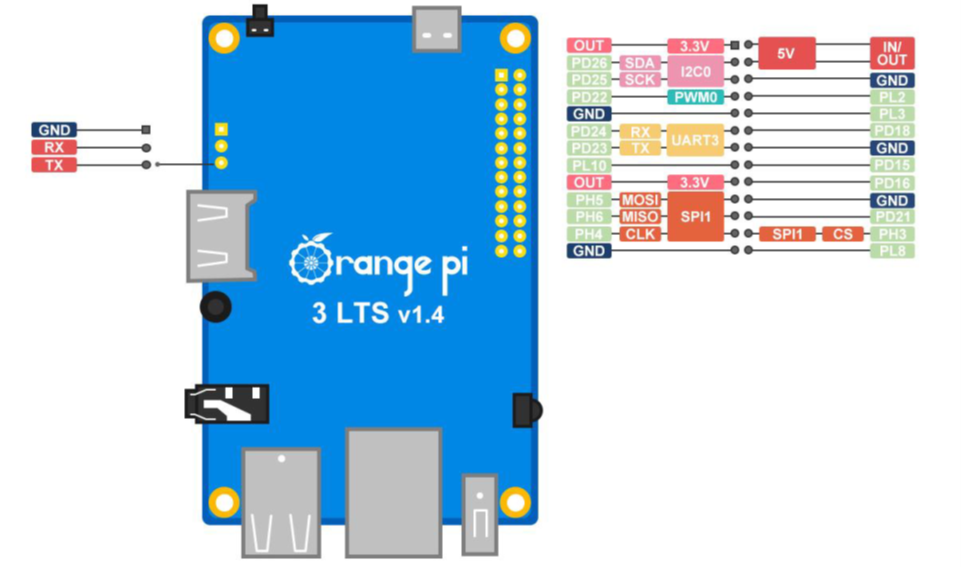
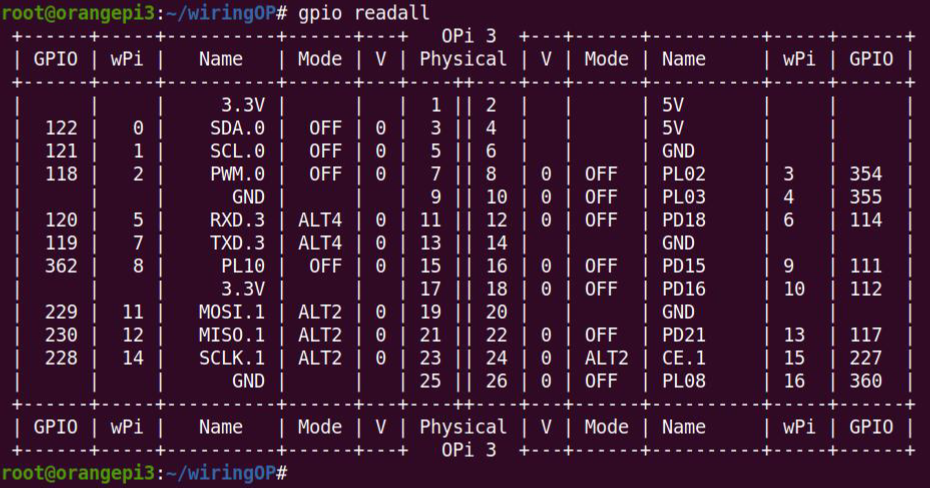
Each pin can have multiple roles, indicated by the following chart:
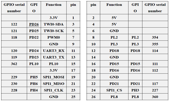
For now we will only use the digital input/output role that is available on every pin except:
- 3.3V & 5V which are pure power supply pins that provide a constant voltage. The voltage level depends on the pin, and it can be either 3.3V or 5V on the Orange Pi 3 LTS.
- GND: A ground pin is a pin that connects to the negative terminal of the power supply. It is necessary to complete some circuits and provide a reference point for the voltage levels of other pins.
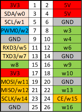
The indications of w0, w1, ..., w16 correspond with the WiringPi GPIO0 through GPIO16.
This chart makes it clearer with color codings:
Understanding Current (I) and Voltage (U)
Now, let's delve a bit deeper into the concepts of current (I), measured in Ampère (amps) and voltage (U), measured in Volt (volts). Imagine electricity as the flow of tiny particles called electrons, moving through a conductor like a wire. Current (I) is simply the measure of how many of these electrons are flowing past a given point in the wire each second. It's like measuring the rate at which water flows through a pipe.

Now, voltage (U) is a bit trickier but equally important. Think of it as the driving force behind the flow of electrons. It's what pushes those electrons along the wire, similar to how pressure pushes water through a pipe. Voltage (U) is often compared to electrical pressure because it represents the potential energy difference between two points in a circuit. When we have a higher voltage, it means there's more potential energy available to push those electrons, just like higher water pressure can push water through a pipe more forcefully.
To put it in simpler terms, think of a hose connected to a tap. When you turn on the tap, water (analogous to electrons) starts to flow through the hose (our conductor). The force with which the water flows depends on how much you open the tap (voltage - U) and how wide the hose is (resistance, which we'll discuss another time). Similarly, in an electrical circuit, the flow of electrons (current - I) depends on the voltage (U) applied and the properties of the circuit.
How GPIO Pins Work
Now, let's relate these concepts back to our Orange Pi 3 and GPIO. When we talk about a pin being in a "high" state, it means that the voltage (U) applied to that pin is relatively high, creating a potential difference between that pin and the ground (a reference point in the circuit). This potential difference is what drives the flow of current (I) through any components connected to that pin.
In the context of GPIO, when a pin is set to "output" mode and in a "high" state, it's like flipping a switch to turn on a light. Electricity flows from the pin to the connected component, illuminating the pathway for current to travel. This state allows the GPIO pin to actively control external devices, such as LEDs, motors, or relays.
Conversely, when we set a pin to "low", we essentially bring its voltage (U) close to zero, eliminating the potential difference and stopping the flow of current (I). In the GPIO realm, this is akin to turning off the switch. The pin is now in an "output" mode but in a "low" state, meaning it's not actively supplying voltage to external components.
Now, let's consider the scenario where a GPIO pin is set to "input" mode. In this state, the pin is like a sensor, waiting to detect changes in voltage. When the pin is in a "high" state, it means that the voltage at the pin is relatively high, indicating a logical "1" or "true" state. Conversely, when the pin is in a "low" state, the voltage is close to zero, representing a logical "0" or "false" state.
| GPIO Mode | GPIO State | Voltage Level | Input result |
|---|---|---|---|
| Output | High | VCC | N/A |
| Output | Low | 0V | N/A |
| Input | High | VCC | True / 1 |
| Input | Low | 0V | False / 0 |
VCC = 3.3V in case of the OrangePi 3 LTS
Understanding these input and output states of GPIO pins is essential for controlling and interacting with external devices using the Orange Pi 3. Whether you're sending signals to turn on a motor or receiving data from a sensor, the ability to manipulate GPIO pins opens up a world of possibilities for projects.
Installing and Using WiringPi (Python) for GPIO on the Orange Pi 3
To begin controlling GPIO pins on the Orange Pi 3 using WiringPi, a Python library, we need to install it first. Follow these steps:
Update the package list to ensure you have the latest version of available packages:
sudo apt updateBefore we install WiringPi, let's ensure we have the necessary tools. Run the following command to install Git:
sudo apt install -y gitNow, let's proceed with installing WiringPi. Follow these steps:
Clone the following repository from GitHub. As you can see it is called WiringOP, this is the Orange Pi 3 LTS supported version of WiringPi:
git clone https://github.com/orangepi-xunlong/wiringOPNavigate into the WiringOP directory:
cd wiringOPClean any previous build artifacts:
sudo ./build cleanBuild and install WiringOP:
sudo ./buildTest the install, let's check the GPIO pin layout:
gpio readallThis command displays a table showing the mapping of physical pins to GPIO numbers. Note the pin number you want to use for our example which is GPIO2, called wPi 2 on this table. You can always reuse this command to check a status.
🛠 Using WiringPi to blink the LEDs on a breakout board
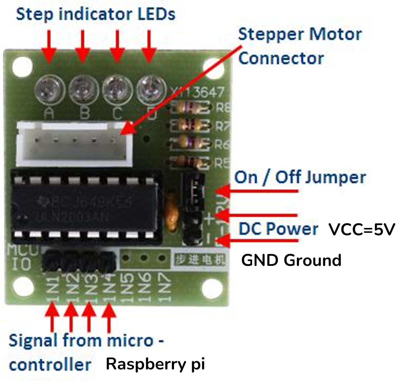
With the Orange Pi 3 version of WiringPi installed, let's proceed with a basic example using an ULN2003APG breakout board connected to the Orange Pi 3.
A breakout board is a circuit board that connects a single electrical component, sensor, or chip to a solderless breadboard. It has labeled pins, small size, and reusability. Breakout boards make it easier and more convenient to use integrated circuits (ICs) that have many pins or are too small to fit on a breadboard. They also have documentation and examples to help you get started with your project.
The ULN2003APG is a breakout board that has a ULN2003A chip on it. This chip can control up to seven devices that need a lot of power, such as motors, lights, and buzzers. It can work with Arduino, Raspberry Pi, and other boards that have 5V signals.
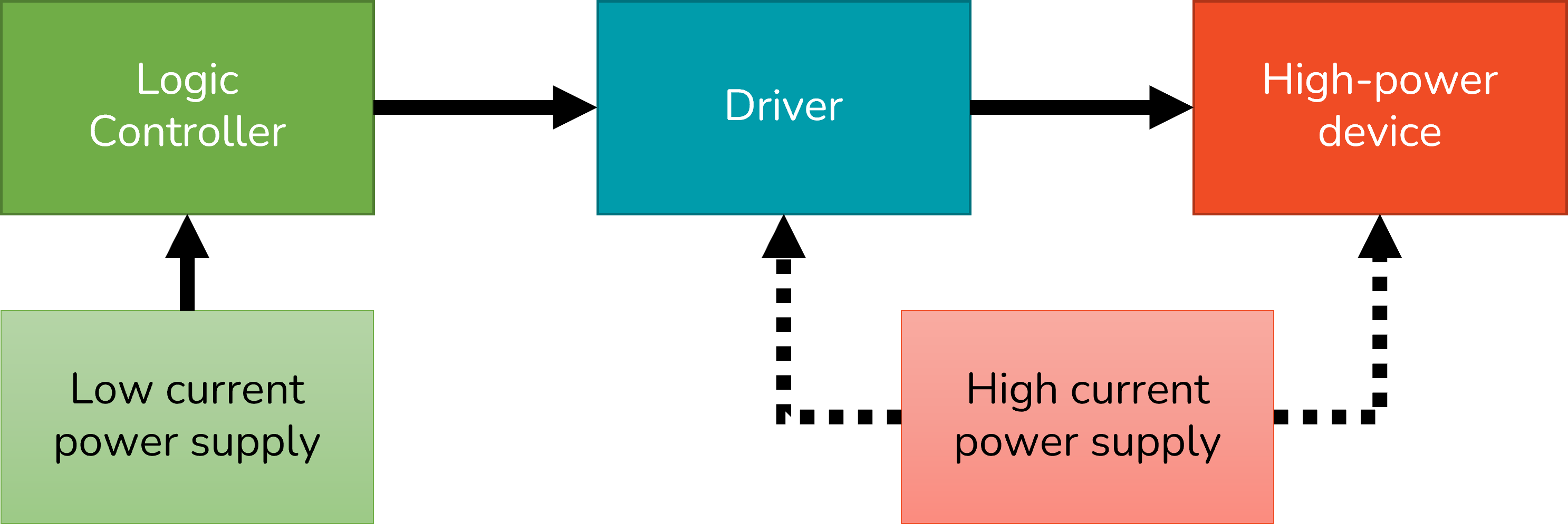
The ULN2003 is a driver, which means it can connect a low-power control circuit (such as a microcontroller) to a high-power device (such as a motor or a relay). The control circuit sends a signal to the ULN2003, which then turns on or off one of the transistors in the chip. This allows the ULN2003 to control the flow of a larger current from a separate power source to the device.
The ULN2003 is useful for driving devices that need more power or voltage than the control circuit can provide. For example, if you want to use a 5V microcontroller to control a 12V motor, you can use the ULN2003 to switch the motor on and off. The ULN2003 also has diodes built-in, which protect the chip and the control circuit from harmful voltage spikes that can occur when switching inductive loads (such as motors or relays).
We will use this board for its intended use later on, but for now we will only use it to blink and light up the LEDs that are on it.
Connect Components
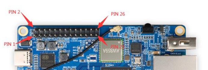
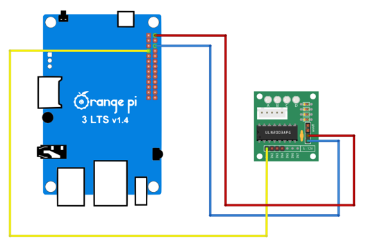
Remembering our Orange Pi 3 pinout we can make our first connection.
Connect 5V (pin 2), Ground (pin 6) and GPIO2 (pin 7), which is named w2 on the chart, in the following way.
Using WiringPi to control GPIO
Now, let's manually control a GPIO pin to light up an LED on the ULN2003APG. We'll use GPIO2 for this example. First, set the pin as an output:
gpio mode 2 outNext, turn the GPIO pin ON to light up the LED:
gpio write 2 1You should see the LED light up. Now, wait for a moment before turning it OFF:
sleep 1  # Wait for 1 second
gpio write 2 0
The LED should now be turned OFF. This simple demonstration showcases manual control of GPIO pins on the Orange Pi 3 using WiringPi through command-line commands.
For further information on available commands and options for WiringPi, consult its manual page:
man gpio